

This is a fairly simple modification to add an extra B-button to your Madcatz controller, model 4165. I can't guarantee that it will work on any other controller, and I take no responsibility if you screw up your own controller following these directions. I apologize in advance for the blurry images. I was sober, but my camera was apparently all hopped up on goofballs... and didn’t have a macro mode that was worth half a crap.
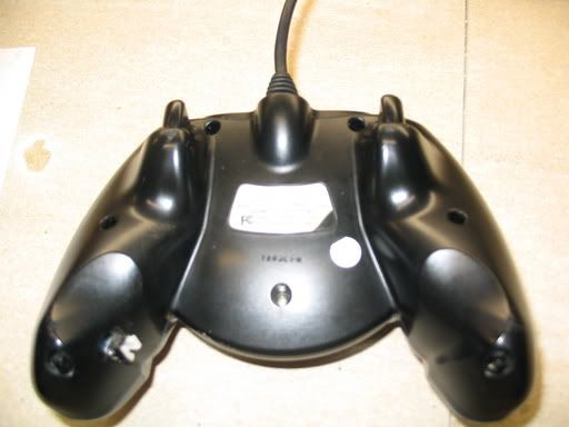
1) Remove the 7 screws in the back of the controller...
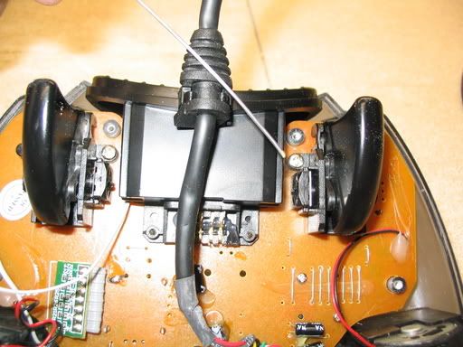
2) Carefully lift off the back of the controller... you may have to wiggle the back a bit to get it over the triggers and get it loose from the memory card holder.
3) Unscrew the two Phillips head screws inboard of the triggers to get the printed circuit board loose from the front cover.
In this pic, the pointer is indicating the right trigger screw.
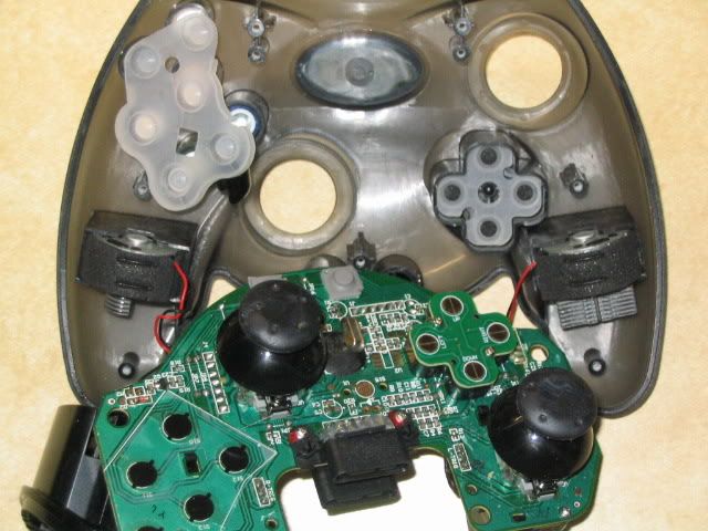
4) flip the pc board carefully back so you can work on the front face of it... there is a silicone pad over the xyab black/white buttons, set it aside or leave it in place on the front cover. All the front cover buttons will be loose now... if one falls out, it shouldn’t be too hard to figure out where to drop it back in...Most of these buttons have a key on the side so you don’t put them in backwards or in the wrong...er... hole
5) find the B button... and follow the narrow trace from the b button pad to the strip of contacts at the base of the nearby ribbon cable.. On mine, the b button was the middle contact on the strip.
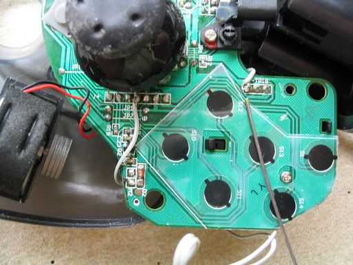
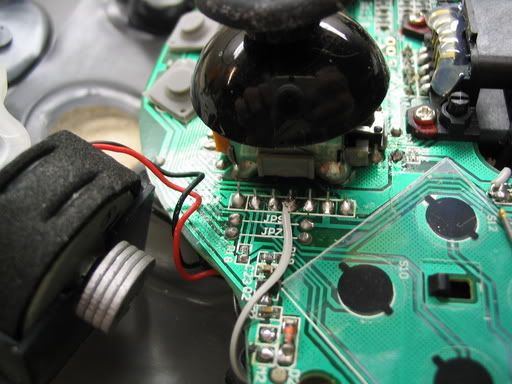
6) Solder a thin wire to this contact... I stripped some old wires from a computer ribbon cable. (Idea stolen from DS). Don’t hold your soldering iron on any longer than necessary, you may damage the pc board or nearby components.
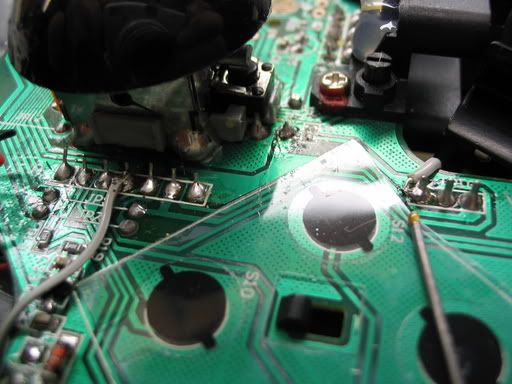
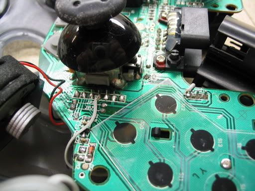
7) Locate the three contacts for the trigger on the same side, and solder your second wire to the bottom one. These photos show both wires in place, the top right is the trigger/common wire.
You'll need a pc board mount momentary switch for your second B button. I used some cheap ugly piece of crap from ASS (American Science and Surplus) that I got for about 1/2 a cent... the handy part of this design is a) the pc board mount switch is glued to the outside of the case, so you dont have to worry about fitting most of the switch inside the case and interfering with the vibration motor and 2) when i get a better switch, i can pop this one off with a pocket knife, solder the wires to the new one and glue it on without ever opening the controller
Drill/dremel/cut/gnaw holes for the leads of you switch to go through the case.. if your switch has no leads that project downwards, sand or otherwise scuff up the area where your switch will go so the glue will hold, and drill a small hole or two for the switch wires I put mind on the inside bottom of the right grip, so I can hit it with the ring finger of my right hand.
9) run the wires around the perimeter of the case, away from any switches, triggers, or the vibe motor, and out through the holes you made in the grip
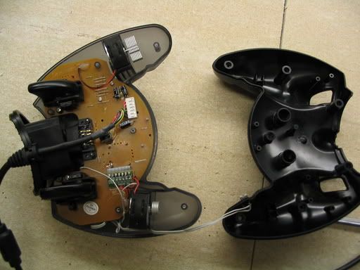
10) solder the wires to the switch make sure the switch leads fit through the holes you drilled, and double check to make sure the wires are not interfering with any moving parts, then glue the switch in place .. I used thick cyanoacrylate glue, but epoxy or a glue gun should work fine as well.
11) Make sure all the silicone pads and buttons are in place, as well as the plastic memory card slot piece, then work your controller back together and close it up.
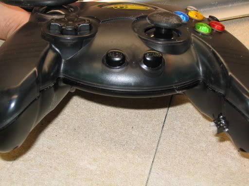
Here’s my finished product:
~ DeadDrPhibes
2) Carefully lift off the back of the controller... you may have to wiggle the back a bit to get it over the triggers and get it loose from the memory card holder.
3) Unscrew the two Phillips head screws inboard of the triggers to get the printed circuit board loose from the front cover.
In this pic, the pointer is indicating the right trigger screw.
4) flip the pc board carefully back so you can work on the front face of it... there is a silicone pad over the xyab black/white buttons, set it aside or leave it in place on the front cover. All the front cover buttons will be loose now... if one falls out, it shouldn’t be too hard to figure out where to drop it back in...Most of these buttons have a key on the side so you don’t put them in backwards or in the wrong...er... hole
5) find the B button... and follow the narrow trace from the b button pad to the strip of contacts at the base of the nearby ribbon cable.. On mine, the b button was the middle contact on the strip.
6) Solder a thin wire to this contact... I stripped some old wires from a computer ribbon cable. (Idea stolen from DS). Don’t hold your soldering iron on any longer than necessary, you may damage the pc board or nearby components.
7) Locate the three contacts for the trigger on the same side, and solder your second wire to the bottom one. These photos show both wires in place, the top right is the trigger/common wire.
You'll need a pc board mount momentary switch for your second B button. I used some cheap ugly piece of crap from ASS (American Science and Surplus) that I got for about 1/2 a cent... the handy part of this design is a) the pc board mount switch is glued to the outside of the case, so you dont have to worry about fitting most of the switch inside the case and interfering with the vibration motor and 2) when i get a better switch, i can pop this one off with a pocket knife, solder the wires to the new one and glue it on without ever opening the controller
Drill/dremel/cut/gnaw holes for the leads of you switch to go through the case.. if your switch has no leads that project downwards, sand or otherwise scuff up the area where your switch will go so the glue will hold, and drill a small hole or two for the switch wires I put mind on the inside bottom of the right grip, so I can hit it with the ring finger of my right hand.
9) run the wires around the perimeter of the case, away from any switches, triggers, or the vibe motor, and out through the holes you made in the grip
10) solder the wires to the switch make sure the switch leads fit through the holes you drilled, and double check to make sure the wires are not interfering with any moving parts, then glue the switch in place .. I used thick cyanoacrylate glue, but epoxy or a glue gun should work fine as well.
11) Make sure all the silicone pads and buttons are in place, as well as the plastic memory card slot piece, then work your controller back together and close it up.
Here’s my finished product:
~ DeadDrPhibes